4 Post Car Lift Installation Instructions: Assembly & Setup Guide

2024-06-01

How Do You Install the 3600kg 4 Post Car Lift Easily and Quickly? You Need to Check Out This Article First!

Installing a four-post car lift involves more than assembling the columns and platform. Before the equipment is operated, the installation site, concrete condition, equipment layout, anchoring, runways, wire ropes, hydraulic system, electrical connections, safety locks, and final adjustments all need to be checked.

This guide explains the 4 post car lift installation process using the SolidParking FP-360 as the reference configuration. It covers the major steps from site preparation and component assembly to hydraulic and cable setup, synchronization, safety testing, operation, and routine maintenance.

Because lift configurations and site conditions vary, the specifications provided in this guide should be checked against the latest model-specific technical documentation and the requirements of the actual project.
Before Assembly:

Packaging

The FP-360 comes securely packaged to prevent damage during transport. The package dimensions are significant, and the total weight is approximately 910kg.

Transport

Transport should be handled by expert personnel using appropriate lifting tools like forklifts, cranes, or bridge cranes. Always check for any damages or missing parts upon arrival.

Storage

Store the lift in a warehouse or a well-protected outdoor area to prevent water damage. Ensure the temperature remains between -25ºC and 55ºC.

Opening the Package

Carefully open the crates to avoid damaging the machine or its components. Ensure all parts listed in the delivery note are present.

4 Post Car Lift Assembly at a Glance

Site and Floor Requirements

Selecting the Site

Ensure the installation site is free of overhead obstructions and has a solid, defect-free concrete floor. The lift is designed for indoor installation only.

Floor Requirements

The lift must be installed on 3000 PSI concrete with a minimum thickness of 150mm and an extension of at least 1.5m from anchoring points.

Foundations

The lift must be securely fixed to the floor to be functional. Before proceeding with the assembly and installation of the machine, verify the floor is of a suitable type to withstand the lift’s full load when in use. Only install the lift on a horizontal floor, free of obstacles. The floor where the machine is to be installed should be level, un-fissured concrete, and at least 12 cm thick, built with a resistance of 25 Nm/mm², and fixed to the bottom of the lift with the aid of eight (2 per column) M10X100 dowels. 

If these conditions are not satisfied, proper foundations must be prepared with a gravel floor with a minimum thickness of at least 50 mm. The user should then lay a steel electro-welded mesh with a quadrant of 10 cm and a wire diameter equal to or greater than 8 mm on the gravel floor. A concrete layer with a thickness of at least 180 mm shall then be placed on top of the mesh.

Tools and Components

  • Rotary Hammer Drill
  • 3/4” Masonry Bit
  • Hammer
  • 4 Foot Level
  • Open-End Wrench Set (SAE/Metric)
  • Socket and Ratchet Set (SAE/Metric)
  • Hex-Key / Allen Wrench Set
  • Large Crescent Wrench
  • Large Pipe Wrench
  • Crow Bar
  • Chalk Line
  • Medium Flat Screwdriver
  • Tape Measure (25 Foot Minimum)
  • Needle Nose Pliers
PowerPack Parts List
The list of Power pack parts
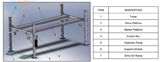
4 Post Car Lift Parts List
The table of parts of 4 post car lift

Column and Beam Assembly

Position of the workstation

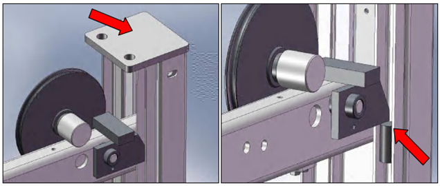
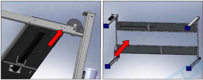
Align the four posts into the appropriate position. Insert the support beams in the four posts. Make sure that while raising the beams/columns, the load is always properly balanced. It is preferable to use a crane to install the lift, but using a forklift is also acceptable. Position the lifting device as close as possible to the load. 

Before moving posts, ensure cables are not trapped below the post base plates. Fit the top plate prior to moving. Raise the support beam to engage on the ratchet and locate the safety block to ensure the beam cannot drop.

Car Lift Installation Tips
Make sure to install the master platform first and not to swap the position of the two platforms. The master platform must be mounted close column where the power pack is installed (master column).
Car Lift Installation Tips

Make sure that all the M16 nuts and bolts are tightened before proceeding with the installation. Start securing the lift to the ground by drilling holes (10 mm diameter X 100 mm depth). Remove any dust & debris before inserting bolts. It is permissible to use packing washers if necessary: maximum 10 mm. Fix the post into position using the supplied bolts and tighten them to the specified torque (163–165 Nm). Align the four posts using a chalk line and position them as specified. Fix the lift to the ground using M10 bolts (not supplied with the machine). Lock the bolts using a dynamometric wrench, verifying that the tightening torque is equal to 80 Nm.

Hydraulic and Electrical Setup

Synchronization cables installation

Position the adjusting nut on the cable approximately halfway along the thread. The locking nut must also be tightened to prevent the adjusting nut from becoming loose while in use. Slide the cables through the support plate located at the end of the lifting cylinder.

Connection of the electric box.

Use a 4-wire cable with a minimal section of 2 mm² for each of the phases and of 2.5 mm² for the ground. The cable shall also have a plug compliant with the locally enforced safety laws. The connection to the electric line should be performed according to the enclosed electric scheme.

Connection of the hydraulic circuit

To prevent possible load fails because of hydraulic failure, a parachute valve has been installed on the lifting cylinder. This valve instantly blocks the descent of the platforms if a hose is accidentally cut. Before using the lift, it is necessary to fill the tank with oil and verify the correct assembly of the hoses connecting the hydraulic power unit to the lifting cylinder.

Final connections to the control circuits.

  • Fit the post covers.
  • Dress both the hydraulic pipe & ducting with plastic cable ties, ensuring they are positioned centrally between the cables to prevent any possibility of chafing.
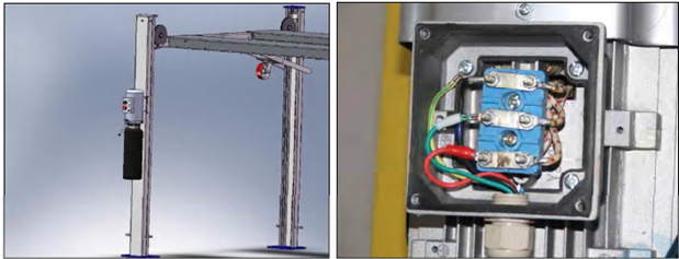
  • Fit the power pack to primary post into position as shown.
220v car lift wiring

Hydraulic

  • Connect the hydraulic lines according to the manufacturer’s hydraulic diagram. Inspect each connection before initial operation and confirm that the system is free from visible leakage.
  • Connect the hydraulic pump to the power pack, ensuring all hydraulic connections are secure.
  • Run the cable from the control box to the power pack. Make connections to motor connector block terminals (U1, V1, W1) and refit the cover plate.
  • Fix limit switch into position.

Synchronization Adjustment and Safety Lock

Preparation Before Adjustment

Ensure the lift is upright and all bolts are tightened.

Adjustment Process

  • Check the power connection and motor rotation.
  • Press the “UP” button to lift the carriage and engage the safety lock.
  • Press the “DOWN” button to lower the carriage.

Synchronization Adjustment

  • Lift and lower the lift several times to ensure the steel cables are properly tensioned.
  • Adjust the cable nuts if necessary.

Loading Test

Check the hydraulic system with a heavy load to ensure proper operation.

Hydraulic pressure provides the lifting force, while the mechanical safety-lock system holds the platform at the selected parking position. Before regular use, verify that the safety locks engage correctly at the intended positions and that the lifting structure remains synchronized during raising and lowering.

Load Testing and Commissioning

Before regular operation, the lift should be tested through a controlled commissioning sequence:

No-load test:
Check smooth lifting and lowering.

Safety-lock test:
Verify correct engagement and release.

Synchronization check:
Confirm that the lifting structure remains level during travel.

Load test:
Verify performance with the approved test/load configuration.

Final inspection:
Check fasteners, cable routing, hydraulic connections, electrical controls, and safety devices

Operation

Control Panel

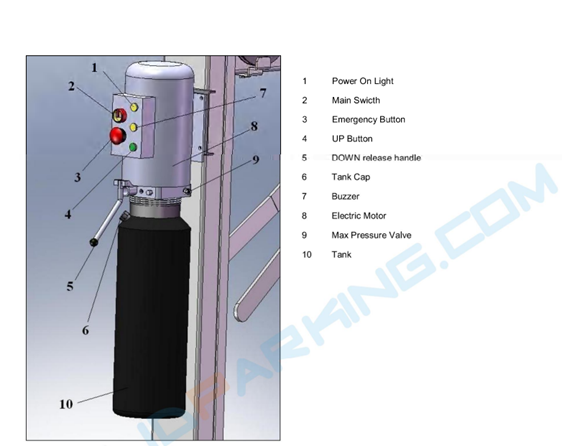
  • Power Switch: Turns the lift’s electric circuit on and off.
  • Lamp: Indicates the electric circuit is powered.
  • Lifting Button: Raises the lift.
  • Lowering Button: Lowers the lift.
  • Lock Button: Releases the safety lock.

To Raise the Lift

  • Position the vehicle between columns.
  • Press the lifting button to raise the lift.
  • Ensure the vehicle is secured and the safety lock is engaged.

To Lower the Lift

  • Press the lifting button to release the safety lock.
  • Press the lowering button to lower the vehicle.
  • Ensure the lift is in the proper position before removing the vehicle.

Manual Emergency Lowering (Optional)

  • Padlock the power switch.
  • Use the emergency hand pump to raise the lift and clear the safety lock.
  • Press the emergency button on the solenoid air valve and unloosen the emergency screw to lower the lift manually.

Maintenance

Maintenance Schedule

  • Weekly: Check support arms and disk adapters.
  • Six Months: Lubricate greasing points and check nuts for correct torque.
  • Annually: Inspect the hydraulic system and check fluid levels.

Annual Inspection

Have the lift inspected by qualified personnel every 12 months.

Maintenance by the Operator

  • Check and replace hydraulic fluid periodically.
  • Lubricate slide tracks every six months.
  • Check the nuts of all anchor bolts every six months.

Cleaning

Do not use high-pressure cleaners or caustic cleaning agents. Periodically wash off aggressive substances and treat the lift with oil or wax spray.

Troubleshooting

Common Issues and Solutions

  • Lift does not work: Check the main switch, power supply, and electrical connections.
  • Lift does not raise: Check for overload, motor direction, hydraulic fluid level, and UP button functionality.
  • Lift does not lower: Check the lowering valve, equalizer cables, and lubrication of sliders.

For FP-360-specific assembly details, including component positioning and cable routing, see our FP-360 installation guide.

FP-360 Technical Reference

Introduction

The FP-360 is designed with a lifting capacity of 3600kg and is suitable for various vehicles, making it ideal for vehicle testing, repair, maintenance, and care.

Intended Use

The lift is specifically designed to lift vehicles and should not be used for any other purposes. Do not use it for washing or spraying vehicles or lifting vehicles exceeding 3600kg.

Layout Dimensions

Refer to the technical specifications for detailed layout dimensions.

Technical Parameters

  • Model: FP-360
  • Lifting Capacity: 3600kg
  • Maximum Length: 5054mm
  • Maximum Width: 2667mm
  • Lifting Height: 2100mm
  • Rated Power: 2.2kw
  • Runway Width: 473mm
  • Lifting Time: 75-85s
  • Post Height: 2438mm
  • Noise Level: ≤70db
  • Packing Dimensions: 5500mm x 534mm x 710mm

Disposal of Used Oil&Machine Demolition

  • Used oil must be treated as a polluting product and disposed of according to legal prescriptions.
  • Demolition should be performed by authorized technicians, and all materials must be disposed of according to current standards.

FAQs

What is required before assembling a 4 post car lift?

The installation area, floor condition, available clearance, vehicle dimensions, electrical supply, and equipment layout should be verified before assembly begins.

How long does it take to assemble a 4 post car lift?

There is no universal slab specification for every four-post lift. Requirements depend on the model, rated capacity, anchoring design, slab condition, and project requirements. For the FP-360 documentation, refer to the applicable manufacturer specification before installation.

Can I install a four-post lift myself?

Installation should be performed by trained or authorized technicians, particularly when anchoring, hydraulic connections, electrical work, synchronization, and safety testing are involved.

This comprehensive guide ensures you have all the information needed to safely and efficiently install, operate, and maintain the FP-360 Four Post Parking Lift. For any additional questions or support, contact the manufacturer or authorized dealers.

qrcode